Enhance your turbomachinery performance and reliability by leveraging the power of digital and embedded expertise.
WATCH NOWIn today’s industrial landscape, failure detection is critical to operational safety and efficiency. Not all key instrumentation issues can be efficiently diagnosed by the conventional onboard electronics, which keeps maintenance teams in the dark and puts operations at risk.
CCC has made the next step in instrument diagnostic technology by combining local device diagnostic with process behavior analysis. This holistic approach helps identify failures by verifying that the process behaves as it would when the device is healthy, or identifying measurements that indicate something is wrong even though the built-in failure detection electronics have not flagged an issue. CCC’s experts have designed these tools to increase safety, minimize process disturbance and maximize reliability.
Available on the Prodigy/S5P/S5Pro and Series 3++ control platforms, CCC’s instrument diagnostic tools help operators reduce the risk of key failures.
Valve Exerciser
Verify the health of antisurge and steam control valves using a partial-stroke test designed to minimize process disturbance.
Transmitter Drift Detection
Detect which of the two dual redundant transmitters failed if their signals start drifting away from each other.
Transmitter Freeze Detection
Identify transmitter freeze, even if the signal remains within the valid range and looks healthy when observed visually.

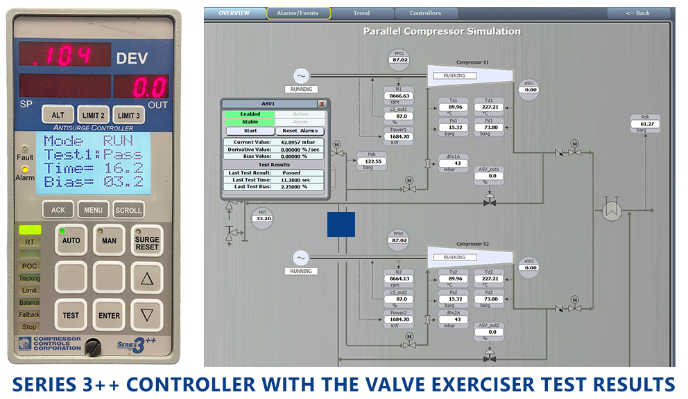
CCC Valve Exerciser
Antisurge valves are key to preventing highly destructive compressor surge events. But even the most high-quality mechanical device lacks 100% reliability, and antisurge valve failures may go undetected because the device is designed to stay closed when the compressor is loaded. The same can happen to the turbine steam valve, which often stays in the same position for long periods of time.
CCC’s Valve Exerciser verifies the health of the most important valves surrounding the compressor in less than one minute — without disturbing the process.
Antisurge valve failure causes and risks
The design conditions for most compressor applications keep the antisurge valves closed, which means that many sites only open these valves during startup and shutdown operations or low-load periods. As a result, control valves can operate in the same position for an extended period of time, ranging from several weeks to even months. While the valve is closed, a range of issues can occur with the positioner, actuator or plug. Maintaining a fully closed position can also cause deposit buildup around the valve stem and seat. This buildup tends to increase stiction, which can prevent the valve from moving without delay when the antisurge or shutdown systems command it to open. And even if it opens, the recycle line can be blocked by hydrates or something else.
Throughout CCC’s commissioning experience, our engineers have witnessed these complex dynamics firsthand — and leveraged them to develop a more effective diagnostic tool.
- In many cases, the antisurge valve fails to open “on demand.” This causes the compressor to surge, which can potentially damage the machine due to increased wear.
- Particularly dangerous are situations in which the valve fails to open on a shutdown, causing repeated surging during the coastdown period.
- There are situations in which the valve stroked normally while the compressor was not operating but failed to respond properly when under a large pressure differential during normal operation.
- Pneumatic actuation system malfunctions such as plugged or leaking impulse lines can also lead to degraded valve performance. In extreme cases, these malfunctions can also trigger a complete failure to respond.
- Excessive tightening of the stem packing can cause jerky valve movement and degraded positioning quality, leading to slow positioning, increased overshoot, or steady-state error.
If mechanical failure prevents the valve from moving when requested or a deposit buildup prevents flow from going through the recycle line, the compressor could surge and cause devastating effects. This scenario also applies to steam turbine main control valves, which stay in the same position for long periods but must move precisely to avoid mechanical damage and process instability.
Limitations of conventional tools for antisurge valve failure
 Although many modern actuators include self-testing features designed to better detect anomalies, invoking such tests without care could introduce instability into the running process. Because the scope of self-tests is typically limited to the actuation system and valve, these tools do not evaluate the system’s effectiveness in controlling the underlying process. In other words, they rarely indicate if the flow is actually going through the pipe — and if they do, this testing won’t be quick or automatic.
With CCC’s Valve Exerciser, users are equipped with real test data and can later analyze the condition of the antisurge valve and steam turbine main control valve during maintenance activities. By doing so, they can prevent process disruptions due to degraded condition of the valve and, in severe cases, machine damage caused by surging or overspeed.
Avoid antisurge valve failures without disrupting the process
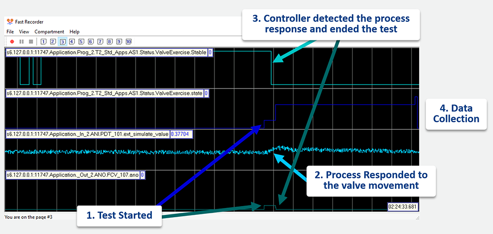
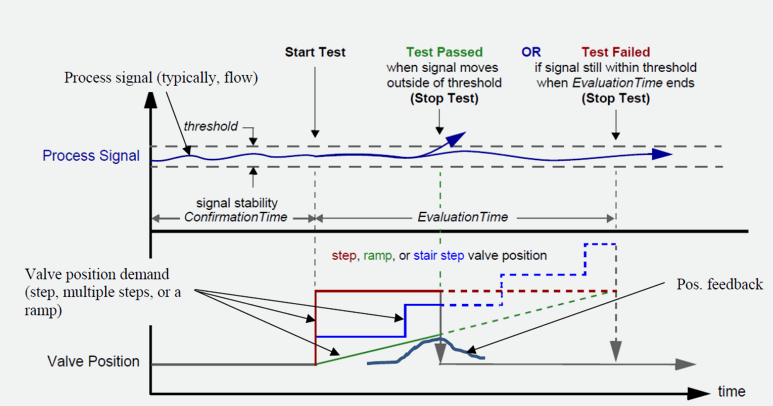
With high execution speed and I/O channels precision, CCC is uniquely positioned to collect all the necessary data involved with the smallest valve movement. To test the valve performance, Valve Exerciser generates a partial stroke test in the steady-state condition. This test evaluates three configurable signals spanning both process parameters and valve position feedback:
Flow (dP) or Speed
Proximity to Surge (DEV)
Position Feedback
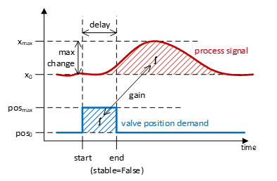 If the Valve Exerciser detects that the process response is below the baseline or the positioning is not fast enough, it generates an alarm that alerts operators to address the valve condition and plan maintenance. This test is designed to have minimal effect on the process, all while verifying valve health in less than one minute.
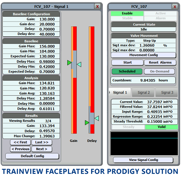
CCC’s advanced diagnostics functionality helps operators enhance not only their detection capabilities but the overall performance of both antisurge valves and steam turbine main control valves. The functionality for Prodigy/S5P/S5Pro controller and for Series 3++ controller are different. Series 3++ contains the valve health test function. On top of that, the Prodigy/S5P/S5Pro version additionally collects information to assess the valve performance.
 Verify valve health by performing a partial stroke test and record process response.
 Detect valve degradation by calculating the magnitude of the process response and the delay between the beginning of the valve movement and first signs of process reaction. If the process responds weaker or slower over time that can be a sign of valve performance degradation.
Reduce the risk of increased stiction through periodic movement of the valve during the partial-stroke test. This stiction is typically caused by material accumulation or hydrates formation around the valve plug.
Avoid process disruption. The partial stroke test makes the smallest possible change in the valve position and quickly returns back to the starting point, so the process reaction will be minimal. The test is only permitted during stable operation when all parameters are under control. The controller performs a standard set of efficient CCC functions that compensate for the mutual influence of the control loops and make the influence of testing on the process negligible.
Generate a historical analysis of valve performance that enables operators to observe and detect long-developing defects and valve degradation, and predict when the valve will most likely start diverging from the baseline performance and original specifications, which could warrant maintenance intervention.
Secure comprehensive operator and engineering interfaces for initiating or aborting a stroke test; monitoring test progress; visualizing current test results and results over preceding periods through historical data; configuring stroke test parameters such as stroking type, ramp rate and maximum opening; and automatically initiating periodic tests.
Implement an automated alarm when the valve performance deviates from baseline by more than the configured tolerance.
This functionality is also available from the DCS with proper MODBUS configuration.
Technical specifications
- Prodigy, S5P, S5Pro and S3++ controllers
- Antisurge (AS) application for both Series 3++ and Prodigy/S5P/S5Pro
- Steam Turbine Speed Control (SC) applications for Prodigy/S5P/S5Pro
- TrainTools version 15.3 and later
- Main faceplate for both Series 3++ and Prodigy/S5P/S5Pro
- Configuration TrainView Faceplate for Prodigy/S5P/S5Pro
- Full set of configuration parameters accessible from Configurator
- All parameters are historized in the TrainView Historian, if installed
- Main analyzed parameters:
- Compressor Flow (for AS) or Speed (for SC) measurements
- DEV (operating point)
- Auxiliary parameter, if available:
- Valve position feedback through current position feedback or HART
- Main calculated parameters, available only for the Prodigy/S5P/S5Pro version:
- Gain, calculated for each of the three signals. Represents process response normalized against valve opening.
- Delay, calculated for each of the three signals. Represents the time it takes the process to respond to the valve movement.
- Requires preliminary commissioning effort by CCC field engineer to set the baseline and configure a few other tuning parameters.
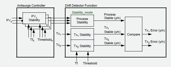
CCC Transmitter Drift Detection (Prodigy/S5P/S5Pro)
 When a transmitter signal drifts, it threatens the accuracy of signal measurements. Faulty measurements can trigger a control system reaction that causes units to go offline, unnecessary recycling and/or a trip. The result is a major process disturbance.
In systems with dual redundant transmitters, one signal’s drift can cause unwarranted actions, despite nominal signal redundancy. This drift can occur for many reasons, from impulse line blockages, moisture or leakage to transmitter malfunction or electrical issues.
CCC’s Transmitter Drift Detection minimizes the risk of process disturbances by precisely detecting transmitter drift in a dual redundant pair — even if the signal remains within the valid range and looks healthy when observed visually.
Shortcomings of conventional drift detection tools
Despite its potential for major process disturbances, transmitter drift often goes undetected by conventional solutions. Because industry practice is to utilize the safest minimum or maximum values for the selection method, the signal often stays within a valid range even when drift is present.
The deployment of smart instruments has improved diagnostic coverage. But despite these advancements, CCC’s commissioning experts have continued to witness a substantial number of transmitter drift incidents.
- Incidents often caused by blocked impulse lines, condensation and/or processor failures within the instrument.
- Differential pressure measurements are highly susceptible to faulty readings due to their relatively low-level signal and sensitivity to distortions caused by impulse line issues.
Detect transmitter drift, every time
When the signals in a redundant pair disagree, CCC Transmitter Drift Detection identifies which one is valid through correlation with numerous measurements, including pressure ratio and flow. This gives operators the information required to prevent the control system from acting based on a malfunctioning signal, which could trigger a process disturbance.
Leveraging unparalleled commissioning experience, CCC designed our algorithm to overcome key limitations of conventional diagnostic tools:
- Identify faulty measurements when the transmitter lacks diagnostics
- Deliver precise accuracy even in cases when the signal appears to be electrically healthy
Available only for dual redundant transmitters.
CCC Transmitter Freeze Detection
Also called a “stale” signal, transmitter freeze can be caused by plugged or closed impulse lines, or a transmitter malfunction that causes the signal to remain at a constant value. But no matter the cause, this significant failure prevents the control system from reacting to process changes, leading to unsafe conditions that require immediate intervention from operation personnel.
 CCC’s Transmitter Freeze Detection algorithm identifies “stale” signals even when they remain within a valid range — and automatically alerts maintenance personnel to the issue.
Conventional instrument diagnostic tools fall short
Despite the significant safety risks of transmitter freeze, the issue often goes unnoticed by conventional detection methods because a frozen signal can stay within a valid range. These solutions are not equipped to identify how signal characterizations change when a transmitter fails to update its output value or when isolation valves on a pressure transmitter are closed.
Spot transmitter freeze before it poses a safety risk
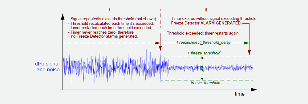
CCC’s Transmitter Freeze Detection tool precisely calculates the amplitude of signal noise, generating an alarm if the figure falls below normal expected values. This timely, effective detection method alerts maintenance personnel to the instance of transmitter freeze and triggers an applicable feedback algorithm that keeps the compressor safe and efficient while operators fix the problem.
CCC is uniquely equipped to understand the nuances of how signal characteristics change during transmitter freeze scenarios. By measuring the amplitude of a signal’s noise, our advanced algorithm identifies when it becomes “frozen” or remains within tolerance for an extended period. This tolerance is chosen to be less than typically observed values.
Can be applied to any transmitter or essentially to any controller input channel.
Failure Detection, Optimized
Contact your sales representative today to discover how CCC’s suite of instrument diagnostic tools can help your operation minimize process disturbance and maximize reliability.